Zero span adjustment of linear stroke valve positioner and installation method of valve positioner
Introduction: The YT-1000L straight-travel electric valve positioner produced by Changyang is used for the slewing operation of an electric controller using an analog signal with a 4-20mA or equal signal range and a pneumatic rotary valve actuator for a control system. With the wide use of the valve positioner, customers often ask Changyang in the work: What is the working principle of the linear valve positioner? Straight stroke valve positioner installation method? How to adjust the position of the valve positioner? How to adjust the span of the valve positioner? How to adjust the valve positioner? For the above issues, Changyang Technology dissects the YT-1000L linear stroke valve positioner and organizes the following six methods. Hopefully, it will help those in need!
A, YT-1000L linear travel valve positioner structure
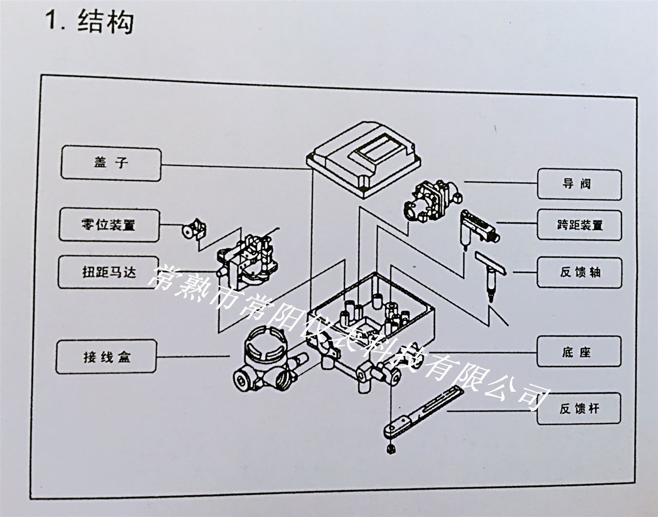 ?
?
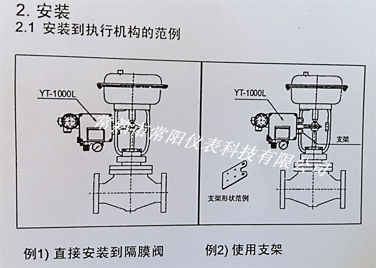
Second, YT-1000L linear travel valve positioner installation
1 Example of installation to an actuator
2 Feedback lever connection
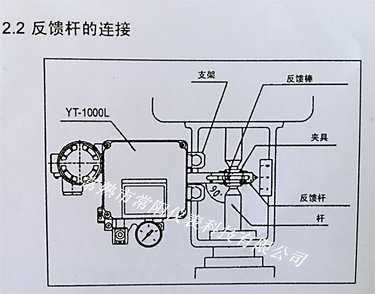
(shown in the figure: YT-1000L linear stroke valve positioner back feedback rod connector)
3 Install to a position where the stem and feedback lever are at right angles when the input signal is 50%.
4 Install to a deviation angle within 10 degrees to 30 degrees.
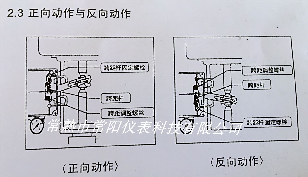
5 positive action and action.
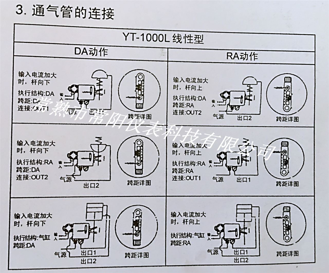
Third, YT-1000L straight-stroke electric valve positioner ventilation pipe connection
1 thoroughly remove debris with a pipe.
2 Use clean gas to completely remove moisture and dust.
3 Use the Chang Yang YT-200 filter regulator to maintain the supply pressure.
4 When the bidirectional operation type is used as a one-way operation type, OUT1 is blocked or OUT2 is blocked, and the pressure gauge must be removed to disconnect it.
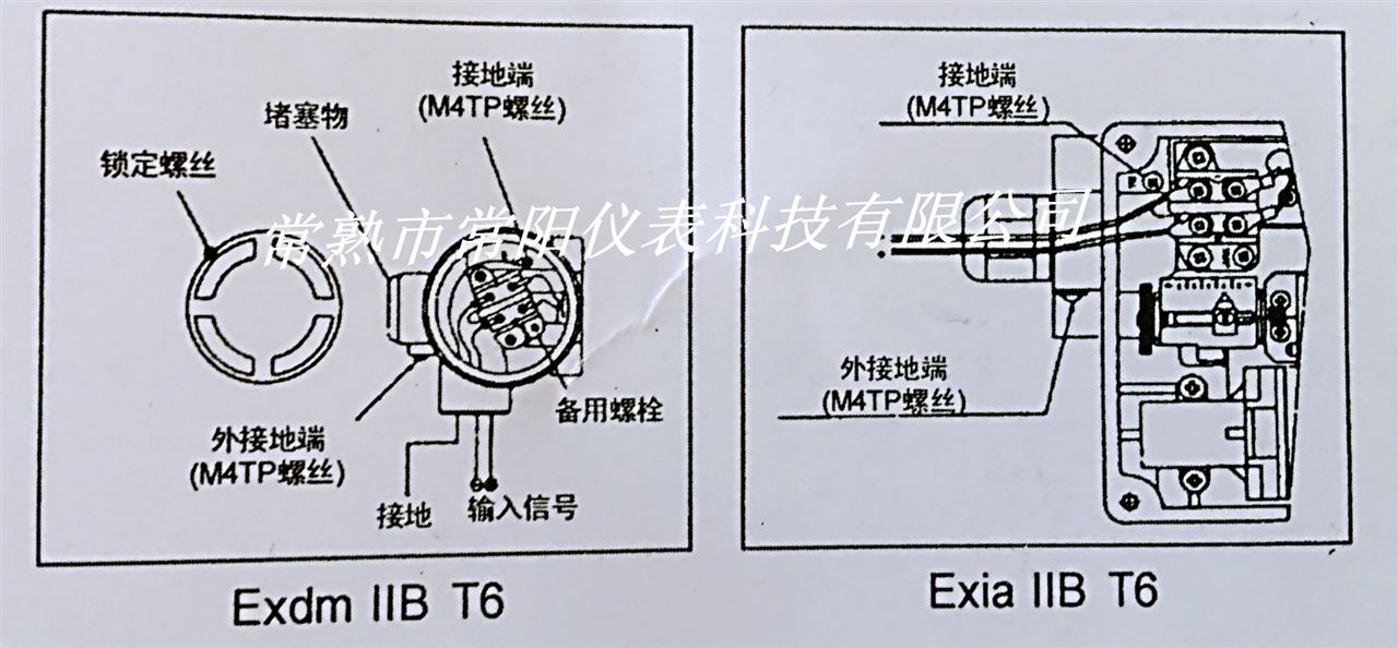
Fourth, YT-1000L linear stroke electric valve positioner electrical wiring
1 Connect the (+) (-) output of the regulator to the (+) (-) input of the positioner junction box.
As for the explosion-proof type, the pressure-sealed wire line connection type and the pressure sealing type can be used.
2 Use a cable gland in the pressure seal packing type (outside diameter = 90-11).
3 Use the PF1/2 (G1/2) specification in the wireline connection type.
4 Close the terminal box cover and lock the locking screw.
5 There is only a spare bolt on the terminal block.
V. YT-1000L Straight Travel Electric Valve Positioner Adjustment
V-1. Check the following before starting adjustment:
1 Check that the piping is properly connected to the pressure delivery port and the OUT1 and OUT2 ports.
2 Check that the wires are correctly connected with the (+), (-) and ground terminals.
3 Check that the actuator is firmly connected to the positioner.
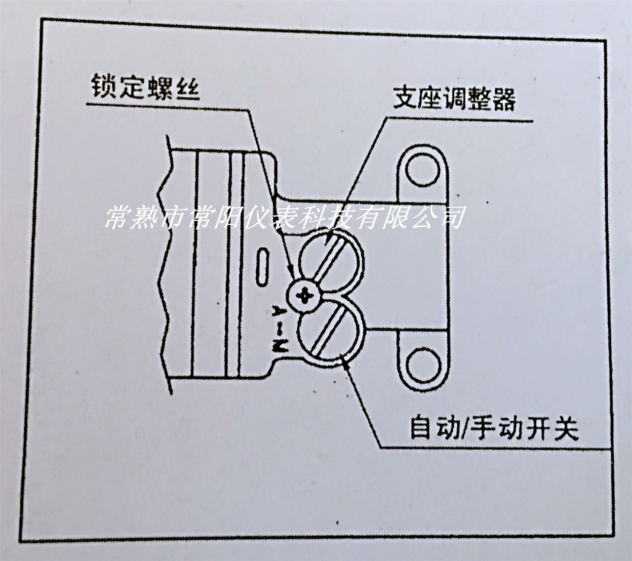
4 Check that the pilot valve automatic/manual transfer switch screws are tight (fully tightened clockwise).
5 Check that the inner feedback span adjustment lever is mounted in the correct position (forward or reverse).
6 Check that the cam surface (forward or reverse) is used correctly and that the flange nuts are securely locked.
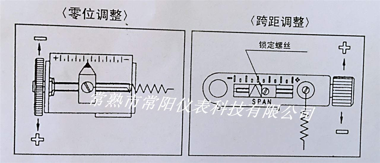
V-2, YT-1000L zero-travel electric valve positioner
1 Set the signal to the start signal of the stroke (4mA), then turn the zero adjuster clockwise counterclockwise.
2 If it is a spring actuator, check if it is set at zero standard pressure. If not, repeat the zero adjustment.
V-3, YT-1000L Straight Travel Electric Valve Positioner Span Adjustment
1 Adjust the span range so that the actuator stops at 0% and 100% of the stroke with 0% and 100% input signals, respectively.
2 Check the zero position and repeat the zero span adjustment. The zero span adjusts the acquisition of the 1/2 separation range.
3 After tightening the span adjustment lock screw.
V-4, YT-1000L linear travel valve positioner automatic / manual switch
1 This is an automatic/manual transfer switch. Changyang factory products are located in an automatic location. To use manual operation, turn the switch counterclockwise.
2 In manual operation, the pressure of Changyang's YT-200 filter regulator is connected to the actuator.
After 3, return the switch to "A" (automatic). Unidirectional operation OUT2 and bidirectional operation are not applicable.
五-5, YT-1000L Straight Travel Electric Valve Positioner Bearing Adjuster
1 No adjustment is required. Changyang products have been adjusted before the factory has been adjusted in the output pressure isostatic position.
2 seat adjusters are often used for two-way action type. If you need to change the isobaric position of the output pressure, use a standoff adjuster.
3 If the actuator has a poor sensitivity to the load, turn the holder adjuster screw clockwise. If unstable, turn the holder adjustment screw counterclockwise. (The amount of rotation varies depending on the actuator. At this time, do not loosen the stopper screw because it is set to avoid escaping the holder adjuster.)
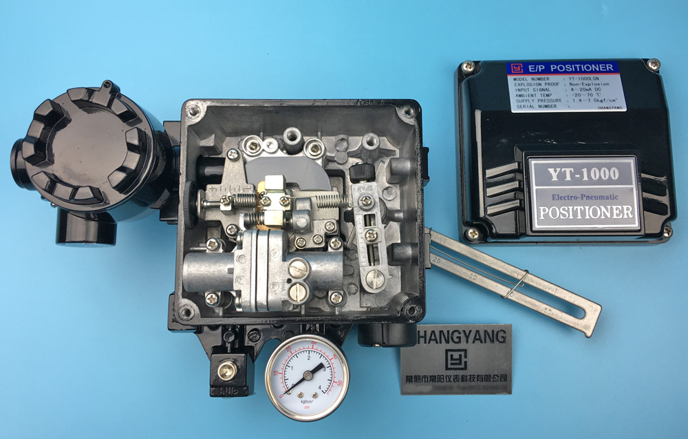
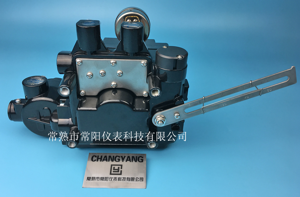
(As shown in the figure: Internal structure of YT-1000L linear valve positioner )
4 If instability occurs due to a small load on the actuator, refer to the selection in Chapter 6.
Six, choose the program
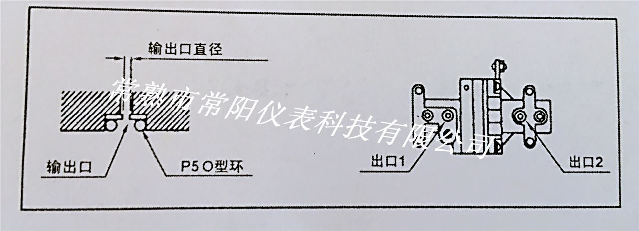
Six-1, YT-1000L linear travel electric valve positioner with output port pilot valve
1Instability may occur when mounting the positioner to a small actuator. In this case, pilot valves with outlets for OUT1 and OUT2 are used. This output is removable.
2 outlet type
Actuator volume diameter of the output port number order 90? Less Φ 0.7 ①90 ~ 180? Φ 1.0 ② 180? ③ no more 3 After pulling out the O-rings from the OUT1 and OUT2 holes, push in the appropriate outlets and then install the O-rings on OUT1 and OUT2. When installing the outlet, be careful not to allow dust and debris to enter the hole.
4 If you are still unstable even after installing the outlet, please contact Changyang meter.
 ?
?
Conclusion: The above seven methods are introduced in detail: YT-1000L linear travel valve positioner structure, linear stroke valve positioner working principle, valve positioner feedback lever connection method, valve positioner ventilation pipe connection method, valve positioning Introduction of the electrical wiring of the device, zero adjustment of the valve positioner, adjustment of the span of the valve positioner, adjustment of the valve positioner holder, automatic and manual switch of the valve positioner, and installation option of the valve positioner to the small actuator. If you are still somewhat confused after reading the above, please contact: Changshu City, Chang Yang Instrument Technology Co., Ltd.
?
Super-Efficient gravure printing machine,Rotogravure Printing Machine,Rotogravure Printing Machines,Rotogravure Printing Machine Fully Automatic
Ningbo New Glory International Trading Co.,Ltd , https://www.newglorymachine.com