1 During the test of an engine, the accumulated work was carried out for 66 minutes, and the third decomposition inspection was carried out. It was found that two teeth of the transmission shaft gear were broken, and the other teeth had different degrees of wear. No damage was found with the matched gears. . The heat treatment process of the drive shaft is quenched and tempered. After machining, the surface is ion nitrided. The required depth of the nitride layer is 0.2mm0.3mm, and the surface hardness is not less than 750HV0.3. The process of matching the chip gear is after machining. The surface is subjected to carbonitriding, and the surface hardness is required to be 700 HV0.3800 HV0.3, the depth of the layer of the tooth surface and the groove width is 0.25 mm 0.4 mm, and the rest is 0.2 mm 0.45 mm.
In this paper, the tooth profile and tooth direction of the drive shaft and the blade gear are checked. The macroscopic and microscopic features of the gear shaft gear are observed and analyzed, and the metallographic structure and depth of the drive shaft and the plate gear are observed. The microhardness of the surface and the core was tested to determine the fracture properties of the transmission shaft gear, and the causes were analyzed.
2 Test method JSM-5600 scanning electron microscope was used to observe the fracture of the drive shaft. The sample was cut near the fracture of the drive shaft, and the microstructure was observed with an Olympus stereoscopic microscope. The DM-400 microhardness tester was used. Detect the hardness and depth of the drive shaft and the surface of the sheet gear.
3 Test results 3.1 Macroscopic observation of the appearance of the drive shaft as shown. It can be seen that the damage area and position of all the tooth wear marks of the drive shaft are substantially the same, and both are on the meshing surface which is in contact with the piece gear. Two teeth on the drive shaft are broken, and the break occurs at the root of the meshing surface in contact with the blade gear. The surface of the fracture is rough and gray. Individual teeth that have not broken have obvious plastic deformation characteristics.
3.2 Microscopic observation of the fracture The two teeth with the fracture of the transmission shaft are numbered as 1 fracture and 2 fracture, and the microscopic morphology of the fracture is observed under scanning electron microscope. The microscopic morphology of the 1 fracture and the 2 fracture are very similar. Here, only the microscopic morphology of the fracture is described in detail.
1 fracture appearance as shown. The low-fold shape of the fracture is visible. The fracture extends from one side of the tooth to the other, and the fracture is divided into a source zone, an extension zone and a momentary fault zone. The high-fold shape of the source region is as shown in b, the source region is seriously worn, and the side surface of the tooth near the source region has the characteristics of the pit formed by the stripping; the obvious radiation ridge line and the fatigue arc feature are visible in the extended region, and the fracture is expanded. The fatigue strip characteristics of the zone are shown by c, indicating that the fracture property of the fracture is fatigue fracture; the transient fault zone morphology d is mainly characterized by intergranular fracture.
There are cracks on the surface of the tooth adjacent to the 1 fracture and the 2 fracture, and the direction and appearance of the crack are basically the same as the two teeth that have been broken. The meshing marks of the tooth surface where no breakage occurred were conspicuous, and the appearance of the position adjacent to the machining tool mark as shown, indicating that the meshing surface was subjected to a large compressive stress.
At the top of the adjacent teeth of the fractured tooth, the characteristics of the pit formed by multiple peelings are found. The high-fold shape of the pit and the typical fatigue arc feature are visible in the pit. Therefore, it is judged that these pits are surface-generated. Contact fatigue is caused by peeling off the block.
3.3 Infiltration depth and microhardness inspection The penetration depth and microhardness of the drive shaft and the piece gear are checked. The surface hardness of the drive shaft is 750HV0.3, which is at the lower limit of the drawing requirements and the effective penetration depth. Below the requirements of the drawings. The matching surface hardness of the plate gear layer has exceeded the upper limit of 800 HV0.3 required by the drawings, and the depth of the layer is 0.68 mm, which exceeds the requirements of the drawings.
3.4 Tissue inspection Sampling in the radial direction of the drive shaft and preparing the metallographic sample, and observing the metallographic structure after etching with 4 nitric acid alcohol, the matrix structure is normal, the tempered sorbite, the structure has not seen overheating, overburning As for the structural defects, the metallographic structure of the surface nitriding layer can be clearly seen as white nitride. According to the GB11354-1989 steel parts nitriding layer depth measurement and the metallographic examination standard pictures, it can be known. Its vein nitride grade is 35.
The teeth of the gears were taken as metallographic samples, and the metallurgical structure was observed after etching with 4 nitric acid alcohol. The matrix structure was martensite structure, and no microstructure defects such as overheating and overburning were observed in the microstructure, and the surface carbonitrided layer was formed. As shown, white granular carbonitrides are visible on the surface.
4 Analysis and discussion From the micro-fracture characteristics of the drive shaft, it is known that there are obvious radiation ridges, fatigue arcs and fatigue strips in the fracture extension zone, so the fracture properties of the drive shaft teeth are bending fatigue fracture. Bending fatigue fracture is a common failure mode of gear parts, which is mainly related to the force of the gear during the working process and its own fatigue resistance. The bending fatigue fracture of the drive shaft is related to these two factors.
On the one hand, from the perspective of the fatigue resistance of the drive shaft itself, the teeth of the drive shaft and the teeth of the chip gear together form a pair of intermeshing work pairs. For this type of work pair, the hardness matching between the two parts is very critical. the elements of. The hardness of the surface of the part is an important indicator reflecting its resistance to contact fatigue. If the surface hardness of the two parts differs greatly, the lower hardness side will be prone to contact fatigue spalling and many pits will be formed on the surface. From the test results, the surface hardness of the drive shaft teeth is too small, basically at the lower limit of the drawings, and the effective penetration depth is also low; the surface hardness of the sheet gear exceeds the upper limit of the drawings, the surface hardness is high, and the effective depth of the layer is effective. Exceeded the drawing requirements.
This leads to an increase in the surface hardness difference between the drive shaft teeth and the chip gears, and the wear between the two increases, the contact fatigue peeling occurs on the surface of the drive shaft teeth and the mesh gear meshing area, and the transmission shaft teeth are broken. at this point. After the contact fatigue peeling produces pits, a large stress concentration is inevitably formed at the bottom of the pit, so that the load on the teeth is increased, and the fatigue cracks are expanded or even broken.
Therefore, the surface hardness of the drive shaft teeth is low, and the surface hardness of the plate gear is high, which is the main cause of the fatigue breakage of the drive shaft. On the other hand, the surface of the drive shaft teeth has continuous white vein nitride and White net nitride, according to GB11354-1989 steel parts nitriding layer depth measurement and metallographic inspection standard, the nitrided layer nitride of the drive shaft is rated, the level is 35, when the network nitride appears in the layer, It will lead to a sharp increase in intergranular brittleness, which makes the tooth surface prone to spalling, which is also an important factor to promote the early contact fatigue peeling of the drive shaft surface.
In summary, the transmission shaft teeth undergo bending fatigue fracture, and the fracture causes mainly because the surface hardness of the transmission shaft teeth and the surface hardness of the plate gear teeth are not matched, and the continuous network nitride appearing on the surface of the drive shaft tooth is promoted. Another important factor affecting fatigue fracture.
5 Conclusions 1) The fracture property of the drive shaft teeth is fatigue fracture; 2) The contact fatigue peeling on the surface of the drive shaft is the direct cause of fatigue fracture; 3) The surface hardness of the drive shaft is low and the surface hardness of the plate gear is high. It is the main cause of contact fatigue peeling on the surface of the drive shaft; 4) 35 grade white vein nitride appearing on the surface of the drive shaft tooth is an important factor in promoting contact fatigue spalling; 5) Suggested improvement of the transmission The surface treatment process parameters of the shaft and the piece gear enhance the control process.
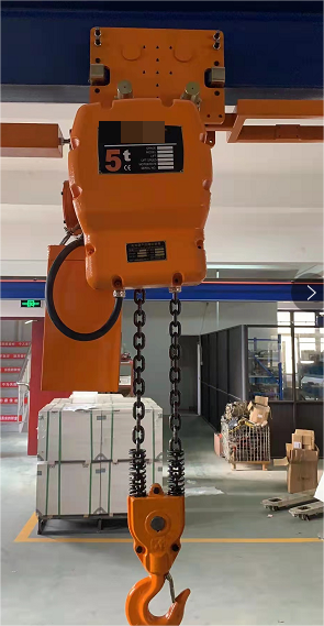
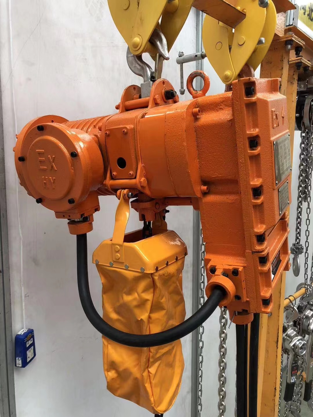
Explosion-proof Electric Chain Hoist
Explosion-proof electric hoist is an explosion-proof lifting equipment designed and manufactured according to my country's new explosion-proof standard. Its explosion-proof form is "explosion-proof" explosion-proof electric hoist. The exposed explosion-proof parts of the hoist are made of special non-sparking materials, and the explosion-proof performance is safe and reliable.
Detailed introduction:
Explosion-proof electric hoists are mainly suitable for various dangerous places of Class I and Class II Class A.B, and the temperature group is T 1 --T 4!
Explosion-proof electric hoist is a light and small lifting equipment. Explosion-proof electric hoist is small in size, light in weight and large in lifting capacity. When the factory building is filled with dangerous mixtures, it can improve working conditions and increase labor productivity under the premise of ensuring safety. The favorable tool is the necessary mechanical equipment for production.
Scope of application:
The electric hoist should be guaranteed to work under the following working conditions:
1. The altitude does not exceed 2000m
2. The relative humidity of the surrounding air is not more than 95% (+25°C)
3. Surrounding medium temperature: -5°C--+40°C
4. In a mine with a vibrant mix
5. In places with significant shaking and impact vibration
6. Pollution level: Level 3
7. Safety category: Class II


Explosion-Proof Electric Chain Hoist,Explosion-Proof Electric Chain Hoist With Trolley,4 Class Explosion-Proof Electric Chain Hoist,Class Iiii Explosion-Proof Electric Hoist
Hengshui Tianqin Import and Export Trade Co.,Ltd , https://www.itahoists.com